- 您现在的位置:买卖IC网 > Sheet目录233 > LXN1240-6M1 (Power-One)DIN RAIL 458W 25.68V BATT CHARGR
�� �
�
�X� Series� Data� Sheet�
�?�
�Table� 17:� Option� board� M2�
�375,� 500� Watt� AC-DC� and� DC-DC� DIN-Rail� Converters�
�When� V� o� is� lower,� the� D1� signal� output� is� high� impedance�
�Function�
�R�
�D2�
�D5�
�D-adjust�
�Description�
�Output� voltage� adjust� 1�
�Input� voltage� monitor� V� i� low�
�Output� voltage� monitor� 1�
�(battery� deep� discharged):� V� o� low� D5�
�Adjustment� of� trigger� values� D1� and� D5�
�(open-collector,� max.� 58.6� V).� In� double-output� models,� D1�
�monitors� only� output� 2� (� V� o2� ).�
�In� applications� without� battery-buffering� the� D1� signal� may� not�
�be� suitable,� since� smaller� dynamic� load� changes� may� cause�
�D1� to� trigger.� For� such� applications,� D5� with� a� trigger� level� of�
�approx.� 85%� of� V� o� nom� should� be� chosen� (e.g.,� for� a� bus� voltage�
�of� 24.7� V:� trigger� level� at� 21� V).�
�1�
�In� double-output� models,� only� output� 2� is� concerned.�
�D5:� System� Volt.� Monitor� (Battery� Deep� Discharge)�
�Multiple� Options� M1� or� M2�
�The� option� board� is� suitable� for� applications,� where� several�
�options� are� needed.� Option� M1� is� standard� for� battery� charger�
�models,� option� M2� is� suitable� for� applications� without� battery�
�or� for� simple� applications� with� battery.�
�In� general,� the� multiple� options� M1� or� M2� are� connected� to� an�
�additional� D-SUB� connector.� Some� signals� (but� not� option� R)�
�can� also� be� connected� to� AUX1� and� AUX2,� if� the� D-SUB�
�connector� is� not� suitable� to� the� customer.�
�D2:� Input� Voltage� Monitor� (Power� Fail)�
�D2� monitors� the� input� voltage� V� i� .� When� V� i� drops� below� 65±3�
�VAC� or� 92� VDC,� the� D2� signal� output� is� high� impedance�
�(open-collector,� max.� 50� V).�
�When� V� i� is� greater� then� said� level,� the� signal� output� D2� is�
�conducting:� V� D2� <� 1.5� V,� I� D2� max� <� 50� mA.�
�D1:� Output� Voltage� Monitor�
�D1� is� intended� for� monitoring� the� bus� voltage� of� a� battery-�
�buffered� system.� It� indicates� that� the� system� is� powered� from�
�the� battery� and� can� for� instance� be� used� as� warning� signal� or�
�to� switch� off� a� part� of� the� load.� When� the� output� voltage� V� o� (or�
�V� o2� )� is� greater� than� V� o� low� D1� specified� in� table� 17,� the� D1� signal�
�output� is� conducting:� V� D1� <� 1.5� V,� I� D1� max� <� 50� mA.�
�D5� monitors� the� output� voltage� V� o� (� V� o2� in� double-output�
�models)� or� the� lowest� admissible� voltage� of� a� connected�
�battery� (battery� deep� discharge).� The� definition� of� D5� is� similar�
�to� D1,� but� the� trigger� level� is� lower.� When� V� o� (or� V� o2� )� is� greater�
�than� V� o� low� D5� specified� in� table� 17,� the� D2� signal� output� is�
�conducting:�
�V� D5� <� 1.5� V,� I� D5� max� <� 50� mA.�
�When� V� o� is� lower,� the� D5� signal� output� is� high� impedance�
�(open-collector,� max.� 58.6� V).� In� double-output� models,� D5�
�monitors� only� output� 2� (� V� o2� ).�
�In� systems� without� battery� support,� D5� signals� that� V� o� (or� V� o2� )�
�is� going� to� drop� below� a� safe� value.�
�In� battery-buffered� systems,� D5� indicates� that� the� battery� has�
�reached� its� deepest� discharge� level� prior� to� getting� damaged.�
�The� D5� signal� can� be� used� for� instance� to� disable� loads,� save�
�data,� or� to� start� a� controlled� switch-off� of� running� processes.�
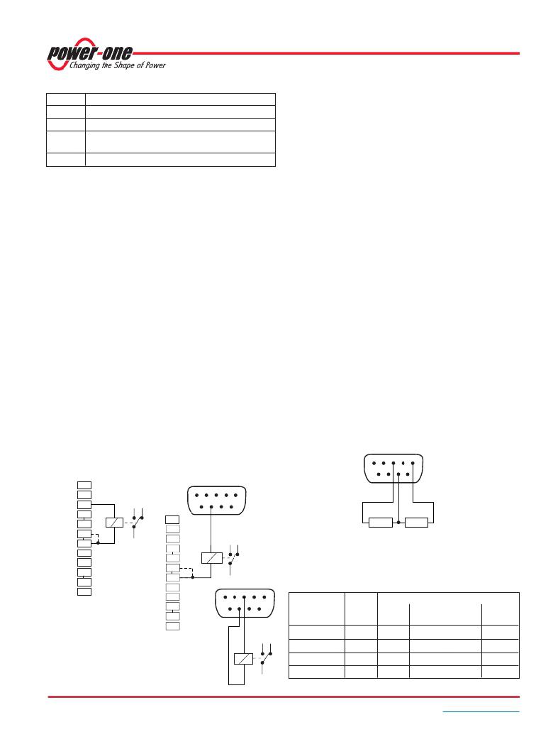
�Adjustment� of� Threshold� Levels� (D� 1� or� D� 5)�
�Pin� 7� of� the� D-SUB� connector� allows� for� adjustment� of� the�
�threshold� levels� of� D1� and� D5.� Both� levels� are� influenced� by� the�
�voltage� divider� R� x� /� R� y.� Resistor� R� x� to� pin� 3� (VCC)� lowers� the�
�levels,� whereas� R� y� to� pin� 1� (GND1)� increases� them;� see� fig.� 19.�
�D-SUB�
�5� 4� 3� 2� 1�
�12�
�AUX2� 11�
�AUX1� 10�
�9�
�8�
�Vo2+� 7�
�or� Vo+� 6�
�5�
�4�
�3�
�2�
�1�
�+�
�Vo2+�
�or� Vo+�
�12�
�11�
�10�
�9�
�8�
�7�
�6�
�5�
�4�
�3�
�2�
�1�
�D-SUB�
�5� 4� 3� 2� 1�
�9� 8� 7� 6�
�+�
�D-SUB�
�5� 4� 3� 2� 1�
�9� 8� 7� 6�
�9� 8� 7� 6�
�VCC� GND1�
�R� x� R� y�
�Change� threshold�
�Fig.� 19�
�Wiring� to� adjust� both� threshold� levels� of� option� D1� or� D5�
�Table� 18:� Options� D1� and� D5:� Trigger� and� switch-on� levels�
�Model� Battery� V� o� low� D1� V� o� low� D� 5�
�V� Bat� trigger� switch� on� trigger� switch� on�
�[V]� [� V� ]� [� V]� [� V]� [� V]�
�LXR/LXN1140� 12� 11.5� 12.1� 10.5� 12.1�
�Fig.� 18�
�Option� D2:� Examples� of� relay�
�control� to� monitor� a� power� failure�
�+�
�LXR/LXN1240�
�LXR/LXN1840�
�LXR/LXN1740�
�24�
�36�
�48�
�23�
�34.4�
�46�
�24.2�
�36.3�
�48.4�
�21�
�31.5�
�42�
�24.2�
�36.3�
�48.4�
�BCD20021-G� Rev� AC1,� 13-May-2013�
�Page� 18� of� 21�
�www.power-one.com�
�发布紧急采购,3分钟左右您将得到回复。
相关PDF资料
M2015LL2G40
SW TOGGLE SPDT LVRLOCK .150 VERT
M2022S2A2G26
SW TOGGLE DPDT BAT KEYWY GOLD PC
M2024TJG03-GH-3A-CF
SWITCH ROCKER SP3T 0.4VA 28V
M2028TYA01-JB
SWITCH ROCKER DPDT 6A 125V
M2039TXA41-DA
SWITCH ROCKER 3PDT 6A 125V
M2113LCW01
SW TOGGLE SPDT RED ILL SILV SLD
M2B25AA5G13
SWITCH PUSH DPDT 0.4VA 28V
M2T23S4A5G30
SW TOGGLE DPDT .300" GOLD RA
相关代理商/技术参数
LXN1240-6M1G
功能描述:DIN导轨式电源 500W X-DIN-Rail Converters SNGL OUT RoHS:否 制造商:Mean Well 产品:Linear Supplies 商用/医用:Commercial 输出功率额定值:960 W 输入电压:180 VAC to 264 VAC, 254 VDC to 370 VDC 输出端数量:1 输出电压(通道 1):48 V 输出电流(通道 1): 输出电压(通道 2): 输出电流(通道 2): 输出电压(通道 3): 输出电流(通道 3): 尺寸:150 mm L x 110 mm W
LXN-1601-6
制造商:POWER-ONE 制造商全称:Power-One 功能描述:375 and 500 Watt AC-DC Converters
LXN1601-6
功能描述:DC/DC转换器 DIN Rail 494W (24.7V) RoHS:否 制造商:Murata 产品: 输出功率: 输入电压范围:3.6 V to 5.5 V 输入电压(标称): 输出端数量:1 输出电压(通道 1):3.3 V 输出电流(通道 1):600 mA 输出电压(通道 2): 输出电流(通道 2): 安装风格:SMD/SMT 封装 / 箱体尺寸:
LXN1601-6D5K2
制造商:Power-One 功能描述:LXN1601-6D5K2
LXN1601-6G
功能描述:DIN导轨式电源 500W X-DIN-Rail Converters SNGL OUT RoHS:否 制造商:Mean Well 产品:Linear Supplies 商用/医用:Commercial 输出功率额定值:960 W 输入电压:180 VAC to 264 VAC, 254 VDC to 370 VDC 输出端数量:1 输出电压(通道 1):48 V 输出电流(通道 1): 输出电压(通道 2): 输出电流(通道 2): 输出电压(通道 3): 输出电流(通道 3): 尺寸:150 mm L x 110 mm W
LXN1601-6K1C2
制造商:Power-One 功能描述:- Bulk
LXN1601-6M2
制造商:Power-One 功能描述:- Bulk
LXN1601-6R
制造商:Power-One 功能描述:- Bulk